Why build a robot cell simulation?
A block moving from point A to point B is a robot demo. It is not electronics manufacturing. For our group project on robots in the electronics industry, I wanted a simulation that looked and behaved closer to a real assembly cell, so I built one in KUKA.Sim 4.10.
I built in two stages. Case 1 placed eight plain blocks on a plain board in a 2 by 4 grid, in about 27 seconds. That proved the pick and place logic. Case 2, covered here, uses real component models and a reject step.
Why a KUKA SCARA
Electronics work is mostly flat. Boards lie on a belt, parts are small, and the robot spends its day moving things down onto a surface and back up. A SCARA is fast and accurate in that plane and compact. What it gives up is payload and flexibility in height, which costs nothing when the part is a resistor or a chip.
I first looked at CoppeliaSim, but its library has no SCARA. KUKA.Sim does, and it runs real KRL programs on a virtual KUKA controller.
| Spec | KUKA KR 6 R700 Z200-2 |
|---|---|
| Axes | 4 |
| Reach | 700 mm |
| Payload | 3 kg rated, 6 kg maximum |
| Repeatability | about ±0.02 mm |
| Speed | up to 157 cycles per minute on the standard test move |
| Controller | KR C5 micro |
| Mounting and weight | Floor, about 21 kg |
Figures are from the manufacturer datasheet as listed by a distributor. I did not measure them.
What is in the cell

The robot carries a two-finger gripper. Beside it sit a tray holding the parts, a flat-bed belt conveyor with a green PCB on it, and a reject bin. I chose a flat belt over rollers because it suits a board better, and the belt is stopped during assembly.
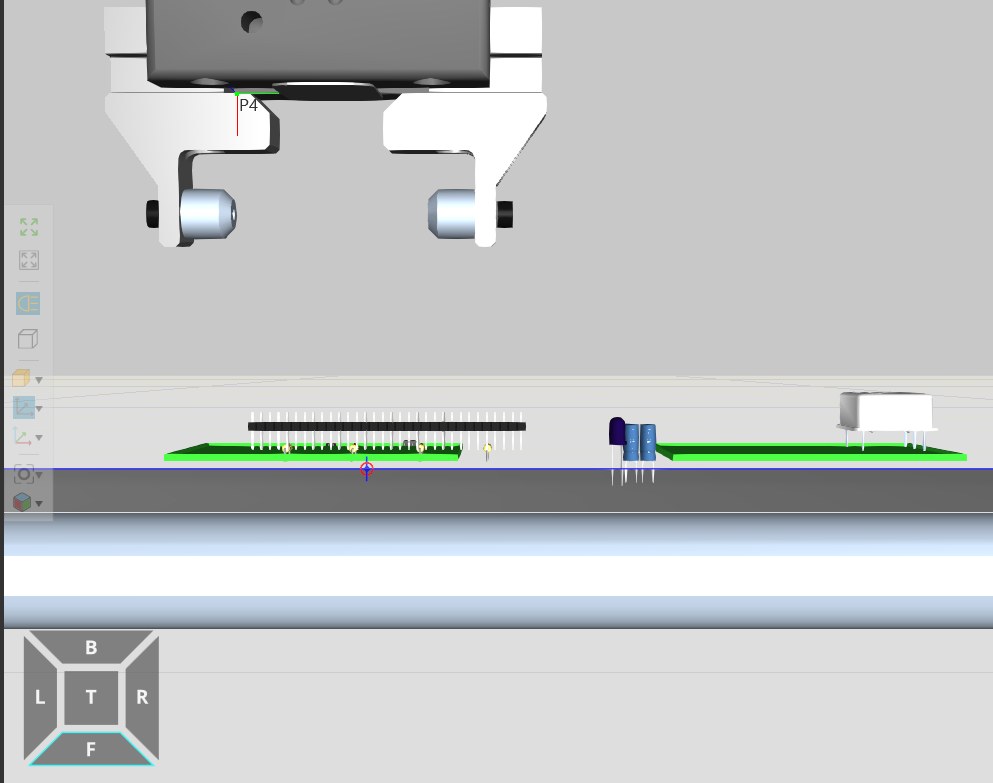
The parts are real STEP models from component libraries: four through-hole resistors, two electrolytic capacitors, an LED, a transistor, a 0603 capacitor, two SOIC-8 chips, a 32-pin header and a crystal oscillator. Each is rotated so its leads point down at the board.
How the robot is programmed
One KRL program runs the whole cell. A timer starts, then a double loop places the first eight parts. The loop counters build each pick and place position, so one short block covers a 2 by 4 grid. The rest of the parts use explicit coordinates, and one chip is rejected.
DEF MAIN()
DECL INT I, J
DECL REAL DZ
DECL E6POS PK, PP
TOOL_DATA[1]={X 92,Y 0,Z 17,A 0,B 0,C 0}
$TOOL=TOOL_DATA[1]
$BASE=BASE_DATA[1]
$TIMER[1]=0
$TIMER_STOP[1]=FALSE
FOR J=0 TO 1
FOR I=0 TO 3
PK={X 405, Y -265, Z 90, A 0, B 90, C 90}
PK.X=405+30*I
PK.Y=-265+30*J
PP=PK
PP.X=420+20*I
PP.Y=235+30*J
IF J==0 THEN
DZ=3
PP.A=90
ELSE
IF I<2 THEN
DZ=-3
ELSE
DZ=2
IF I==2 THEN
PP.X=455
ENDIF
ENDIF
ENDIF
PTP PK
PK.Z=27
LIN PK
$OUT[101]=TRUE
PK.Z=90
LIN PK
PTP PP
PP.Z=22+DZ
LIN PP
$OUT[101]=FALSE
PP.Z=90
LIN PP
ENDFOR
ENDFOR
; ... six more pick and place moves follow, including the reject ...
PK={X 450, Y 250, Z 90, A 0, B 90, C 90}
PTP PK
WAIT SEC 1.5
; ...
$TIMER_STOP[1]=TRUE
;@PRINT Board time ms = {$TIMER[1]}
ENDSet up the tool and the timer
TOOL_DATA[1], and start timer 1. Declarations must come before anything else in KRL.Loop over the grid
FOR loops compute each pick position from the counters I and J, and each place position on the board.Pick and place pattern
PTP, drop straight down with LIN, close the gripper with $OUT[101]=TRUE, lift, move over the board, lower, open the gripper, lift.Adjust for part height
IF block sets a height offset DZ for each case.Reject one chip and stop the timer
WAIT SEC 1.5, picks one SOIC-8 chip and drops it in the reject bin. At the end the timer stops and prints the board time.Six problems and how I fixed them
Parts floated or the wrong part came along
Parts sat to one side or sank into the board
Wider parts were not picked up
KRL is strict about order
INI line broke the parse.Save only after a reset
Plain shapes first, real parts second
Cycle time and what it means
I timed the run by stopwatch, from pressing Play to the robot's last move, because the built-in timer did not show a readable value in my final setup. Case 1 took about 27 seconds for eight moves.
Dividing 3,600 by 44 gives about 82 boards an hour. Do not use that in a business case. It is an ideal run with no vision, no board handling, no gripper wear and no faults, so treat it as an upper bound.
What the simulation does not do
It has no vision system and no real inspection, so the reject is a fixed step and not a detection. It has no feeder, no part variation, no gripper change and no safety fencing. The belt is stopped, so the board stays fixed while the robot works. KUKA.Sim cannot rescale imported parts, so the long leads on the capacitors and LED were sunk 5 mm through the board to look right, which changes the picture and not the cycle time. Positions were set by eye from several views, not against a physical cell.
Where I would take it next
The obvious gap is the inspection. Replacing the fixed reject with a camera-based check would make the cell behave like a real one. After that I would feed boards in on the belt so the cell runs continuously, and compare the SCARA with a six-axis arm on the same job. The wider context, costs and payback evidence are in the full robots in electronics project.